 |
||||||||||
 |
||||||||||
|
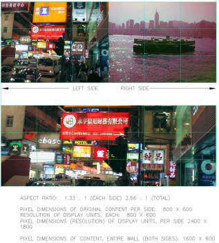
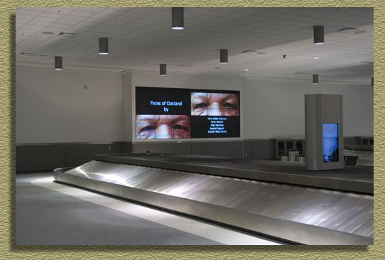
Hardware Narrative for the Media Wall Below is a description of the Media Wall designed to display the media artwork in the newly built baggage claim area at Oakland International Airport.. Media Wall System and Video Wall Processor The Media Wall system is one 3 x 6 display, managed by two processors. Each processor manages one RGB source and output this signal to the left and right 3 x 3 display, with the two 3 x 3 displays combined to form the 3 x 6 display. The combination of these two signals allow the display to be either two separate 3 x 3, or one large 3 x 6 display, producing combinations as depicted below.
The Media Wall systems consists of eighteen (18) media wall projection-type display cubes, with a minimum resolution of resolution of 640x480 (800x600 max) per cube. The Media Wall cubes are capable of powering up, down or into a sleep mode by either the detection of the presence or absence of a video signal or via a control interface. The Media Wall cubes have a depth greater than 57 inches or a weight greater than 187 lbs per cube. The cubes will be accessed from the front for regular maintenance. Each 3x3 cube display (left and right) will include a 3x3 video wall processor. The Media Wall processors are capable of accepting an RGB type video source. The processor will be able to display the source content across the Media Wall cubes, utilizing the full display area of each cube without loss of image area or image content. The Media Wall processor has the ability to accept a control signal, via serial protocol to manage internal effects and settings. Video Servers and Production Computer Two video servers distribute RGB video to each 3x3 video wall processor. The video processing software is Dataton Watchout software, latest commercially available release. All hardware license keys are provided as required to enable full functionality of the software for the intended use. The media content source device (Production Computer Laptop) is a media production computer running the Dataton WatchOut media software for the entire 3x6 display. The production computer meets the specifications issued by Dataton for suitable performance for operating the Watchout software. The production computer must be of a commercial or industrial grade. The production computer communicates and controls the two video servers via a network switch. In addition, the production computer has an on board network interface, both wired and wireless, and serial port, and runs Windows XP-PRO as standard operating system. Media Content Creation and Playback The system is pre-programmed to play back media video files against a calendar based time clock. The artist media files will be placed into a Watchout show file which intern will be scheduled to playback at specific times during the day. The show file may also continuously “loop” if desired. The artist media files may be created as Quicktime or Windows Media 9 video files. Both Apple and Windows based files will be acceptable. Watchout can playback moving images in a Windows Media (DirectShow) or QuickTime-compatible format including MOV, WMV, AVI, DV, and MPEG-2. The artist will need to create two movie files (left and right) for their show. The Watchout software will playback both movie files in sync. Only the display server will render moving images. The production computer will display a static icon representing the moving image. This icon is taken from the Poster Frame of a QuickTime movie file which is the first frame of a movie. The production computer will control the two video servers for playback. For further information about creating movie files that will be compatible with this media display system, please visit www.watchout.com and download the Watchout User’s Guide. A full explanation for file creation is available. Show Control The show control system must be a Windows 2000 or greater based system employing an industrial-grade rack-mount computer using Electrosonic ESCAN software, most current version. One of the Watchout media server computers may also perform dual duty for the ESCAN show control. The computer will have the necessary Input/Output (I/O) to support the ESCAN features for this project, have rack-mount keyboard / mouse drawer and a rack-mount monitor. The show controller (computer) interface with a digital and serial I/O module, which in conjunction with the ESCAN computer, will be capable of managing all start/stop, power up, power down, synchronize and similar functions. This device will be a Mediasonic MS9025 or functional equivalent. Refer to Concept Sketch No. 2 for an interconnection diagram. |
||||||||||
|
|
||||||||||
|
||||||||||